We wanted to improve the support agent’s ability to solve end-user’s problems and issues, so we integrated voice and video calling into the yellow messenger platforms set of solutions to improve customer sat and also the communication between a business and their end users.
Let’s move onto what exactly webRTC is.
It is a technology that enables data, video, and even screen-sharing using a Peer-to-Peer (P2P) connection, meaning the data doesn’t even need to go through a server.
- It offers real time communication from browser
- It also provides a media engine (codecs and media processing, ability to send and receive media in real time) with javascript apis
webRTC is both a browser technology i.e. standard specification and a software stack i.e. open source project.
- webRTC 1.0 -> standard defined by the IETF and the W3C
- webRTC.org -> open source google project, an implementation of webRTC specification.
It reduces friction for users communication because there are no plugins, no downloads, just a URL needs to be shared. It reduces barrier of entry for new devs of the wealth of info that is available as well as the open source implementation on GitHub.
webRTC has become the defacto standard for real time communication used by Google, Microsoft, Facebook, and Cisco. webRTC is a tried and tested solution, and it is advisable that anyone trying to enter such a market uses it.
webRTC has two main ingredients:
- client i.e. browsers
- Servers: there are 4 types of webRTC servers you need to know about:
- application servers – essentially the website hosting the service
- signaling server – how clients find each other and connect to each other
- NAT traversal servers for webRTC – servers used to assist in connecting through NATs and firewalls
- webRTC media servers – media processing servers for group calling, recording, broadcasting and other more complex features. webRTC media servers are servers that act as webRTC clients and are termination points for the media where we’d like to take action.
The webRTC spec has been implemented in all major browsers including Chrome and Firefox and consists of 3 major APIs, there are more but these are the most important:
getUserMedia, which allows a web browser to access the camera and microphone and to capture mediaRTCPeerConnection, which manages the peer-to-peer connection, method to manage and monitor, encodes/decodes media, sends over networksRTCDataChannel, which allow browsers to share arbitrary data
Media Devices can be accessed with JavaScript on your browser through the navigator.mediaDevices object.
The html portion of this demo is very simple, it just contains a video elements that autoplays. (If you dont set it to autoplay you will just get a single frame and that’s not what we want). If we look at the JavaScript code as above for this demo, the most important section is where we are actually using the getUsermedia API.
We can also pass in different types of constraints, so we can just start with simple ones to test it out. So if you try running this with the mediaStreamConstraints passed in, you can see that the video from your camera will be displayed on the screen. and you can also see that we have received a media stream object from the function. This code prints it out on the console. Looking into this object, we see that it has many attributes, let’s try getting the video track from this stream using localStream.getVideoTracks() We can see that the mediastream contains a single video track, similarly if we edit the constraints, we could also look at the audio tracks available in the media stream. Having a media stream object can be very useful as tracks in a media stream are synced ie video and audio.
There are many different types of constraints that you can apply on the media that you request. One particularly useful one could be the dimensions. we can set that also. So let’s try that out by passing the hdConstraints object into getUsermedia. We can see that the displayed video is much larger than before and is exactly the size that we requested. But what happens if you ask for something that is not available. Obviously an error is thrown, but if we look into the log we see that there is an OverConstrainedError and the error message also contains the offending attribute, in this case it is facingMode, as this computer does not have a camera that is labelled as such.
Now that we know how to capture the stream from a media device. Let’s talk once more about The RTCPeerConnection. This interface represents a webRTC connection between a computer and another peer. It provides methods to connect, maintain and monitor the connection, and close the connection once it’s no longer needed.
Before a P2P connection can be made, a process called Signaling must first occur. it just means a way to figure out through which IPs the media should flow between the two peers. This involves a lot of back and forth from clients to the server, with the goal of each client having the other client’s IP address and all other related information regarding the data that each peer wants to share.
Signalling is not defined by webRTC standards, so it’s up to the developer to determine how to setup signaling. We use plain HTTP REST api calls for signalling currently at YM. (although other options are available like SIP, or WebSockets)
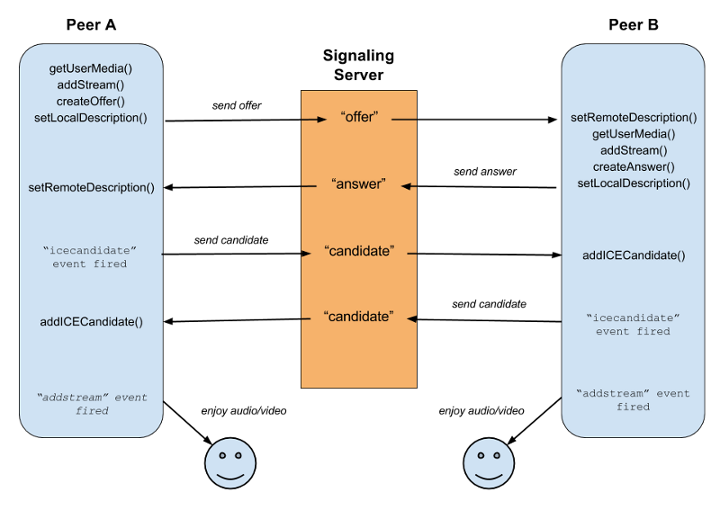
Let’s go into how to actually set up a call in webRTC.
-
as we saw before, the caller Peer A will call getUserMedia to capture the local Media using [navigator.mediaDevices.getUserMedia()
-
The caller will create an RTCPeerConnection object and call [RTCPeerConnection.addTrack()] / [RTCPeerConnection.addStream() [deprecated]. this is to add a new media track to the set of tracks which will be transmitted to the other peer.
-
The caller calls[ RTCPeerConnection.createOffer()] to create an offer.
- So what exactly is an offer? When a user starts a webRTC call to another user, a special description of the call is created called an offer. This description includes all the information about the caller’s desired configuration for the call. The recipient then responds with an answer, which is a description of their end of the call. In this way, both devices share with one another the information needed in order to exchange media data.
- Both the offer and the answer are formatted as an SDP (session description protocol). Let’s just quickly look into the format of an SDP. There is a great resource for exploring this at webRTChacks.
An SDP is a declaration, by a media endpoint, of its receiving specifications and capabilities and a typical declaration would tell us:
- which IP Address is prepared to receive the incoming media stream
- which port number is listening for the incoming media stream
- what media type the endpoint is expecting to receive (generally audio)
- which compression encoding the endpoint is capable of decoding (codec)
- Each peer, then keeps two descriptions on hand: the local description, describing itself, and the remote description, describing the other end of the call.
-
Parallel to the offer answer mechanism, some network information also needs to be exchanged between peers. This is handled using the ICE framework (interactive connectivity establishment).
It’s a way to overcome the complexities of real-world networking. ICE tries to find the best path to connect peers. It tries all possibilities and chooses the most efficient option that works.
Having exchanged SDPs, the peers then perform a series of connectivity checks. The ICE algorithm in each browser takes a candidate IP/port pair from the list it received in the other party’s SDP, and sends it a request. If a response comes back from the other browser, the originating browser considers the check successful and will mark that IP/port pair as a valid ICE candidate.
After connectivity checks have finished on all of the IP/port pairs, the browsers negotiate and decide to use one of the remaining, valid pairs. Once a pair is selected, media begins flowing between the browsers.
Let’s go into another demo for actually establishing a webRTC call.
As previously we run getUserMedia and get the video from the caller and display it on the screen. On clicking call, we can see that the RTCPeerConnection gets created and a stream gets added.
Now let’s talk a little bit more about the ICE. ICE first tries to make a connection using the host address obtained from a device.
It also tries to set up direct communication between peers over UDP. If that fails, then it resorts to TCP.
But there is an issue. Network address translators or NATs provide a device with an IP address for use within a private local network, but this address can’t be used externally. Without a public address, there’s no way for webRTC peers to communicate. To get around this problem, webRTC uses a protocol called STUN - Session Traversal Utilities for NAT (STUN).cSTUN servers live on the public internet and have one task — to check the IP:port address of an incoming request and send that address back as a response. This process enables a webRTC peer to get a publicly accessible address for itself and then pass it to another peer through a signaling mechanism in order to set up a direct link.
What if your firewall is extremely restrictive? In that case we use a different server/protocol known as TURN (Traversal Using Relay NAT). TURN servers have public addresses, so they can be contacted by peers even if the peers are behind firewalls or proxies. TURN servers act as the middleman between the two peers and relay a stream of media. However, they are expensive to maintain as they inherently consume a lot of bandwidth.
So let’s look into a small demo: Trickle-ice. It tests the trickle ICE functionality in a webRTC implementation. It creates a PeerConnection with the specified ICEServers, and then starts gathering candidates for a session with a single audio stream. As candidates are gathered, they are displayed onscreen.
There are different types of ICE candidates:
-
host: The candidate is a host candidate is in fact the true address of the remote peer. -
srflx: The candidate is a server reflexive candidate; theipindicates an intermediary address assigned by the STUN server to represent the candidate’s peer anonymously. -
relay: The candidate is a relay candidate, obtained from a TURN server. The relay candidate’s IP address is an address the TURN server uses to forward the media between the two peers.
Another useful widget for webRTC testing is Chrome’s webrtc-internals page. Open up chrome where we have our demo call still running and type in about:webrtc-internals. This is extremely useful for troubleshooting calls.
At YM, we have integrated voice and video calling into our platform using a general purpose webRTC gateway called Janus. The front end related interfaces for RTCPeerConnection in our support agent-facing app and our user-facing widget are abstracted using the janus.js client side library.
The different webRTC servers that we use:
- the clients are the agent on the app and the user on the widget
- the signalling and the media server are colocated in janus
- we deployed a TURN server to act as the traversal utility
Why Janus? It’s open source, well documented, stable and also provides inbuilt SIP support (which others such as jitsi did not seem to have at the time of exploration).
The Janus core provides the functionality to set up a webRTC media communication with a browser and exchange JSON messages with it. There are many plugins that implement different use cases in a modular way.
The specific ones that we will talk about are:
- sip - it is based on the Sofia-SIP library stack. This plugin allows a web user to register at a SIP server, and then start to make or receive calls from other SIP users, including other web users exploiting the same plugin.
- video call - two webRTC peers call each other through the Janus core for media. with registrations.
- video room - implements a videoconferencing unit for Janus, that is basically like audio/video router.
- Streaming - allows webRTC peers to watch/listen to pre-recorded files or media generated by another tool or live media.
How do we record calls?
Recording in Janus is implemented as a dump of all RTP files exactly as they were transmitted: as such, no manipulation is done while recording, and all post-processing is done using a provided script.
- On call hangup, an event is sent to Janus and Janus sends an event to the agents micro-service.
- Agents-service adds the video processing data onto a queue.
- Janus also has the pure rtp files saved to disk. So we use the conversion utility
janus-pp-recto convert the RTP to the opus / vp8 format. - We merge the audio and video of a single peer using ffmpeg.
- We merge the videos of both the users to get a single file for the call.
- We upload this file to blob storage.
- We delete all the original and processing related files.
Scaling Janus
Currently we are running Janus as a single node instance on Kubernetes, but as we have more and more calls this will cause issues.
There are many things we can try:
- plain load balancing (using a random server, round robin, or selecting the closest server to user): But there is a dependency between the two peers here, they need to be on the same Janus instance for the call to go through, that is, we need the context also to be available, and hosting the same room on different servers is an overhead and a little messy.
- context aware resource brokering between the instances can also work
- relaying RTP i.e., video room can publish media to the streaming mountpoint of multiple different janus instances, but similarly to before hosting the same room on different servers can cause issues.